MIL-DTL-25959H
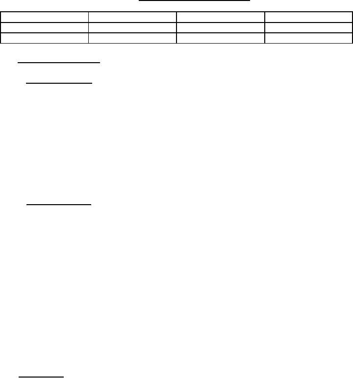
TABLE I. Tie down tensioner dimensions.
Tie down
Length
Width
Height
CGU-8/A
16 inches
4 inches
3.5 inches
CGU-7/A
18 inches
5 inches
4 inches
3.6 Tensioning capabilities.
3.6.1 Tensioning ability. After preliminary adjustment of the tie down tensioner to remove
excess slack in the chain, the tensioning assembly shall be operational and shall be capable of
applying tension to the chain of not less than 300 lbs with a manually applied torque of not more
than 60 inch-pounds acting on the tensioning adjustment control. Additionally, no component of
the tie down tensioner shall fail when torques up to 85 inch-pounds are applied to the tensioning
adjustment control, in the tensioning direction while the tie down tensioner is fully retracted, and
in the loosening direction, when in the fully extended position when tested as specified in
4.6.6.1. Failure is defined as catastrophic as well as permanent deformation of components. The
tensioning adjustment control shall have a minimum height of 1 inch. It shall be of circular
design with raised area to aid grip during tensioning and shall have at least eight locking
positions per 360o rotation.
3.6.2 Tension releasing. The tie down tensioner shall be so designed such that the chain
assembly (component attached to the cargo) can be manually released and automatically
separated from the tie down tensioner with one hand in a single operation with an applied force
not exceeding 50 lbs while restraining loads that apply 5,000 lbs of tension on the chain. It shall
also be possible by the application of additional force not to exceed 100 lbs (for both Types III
and IV devices) to safely release the chain assembly from the tie down tensioner while
restraining loads that apply 10,000 lbs of tension for the CGU-8/A device or 25,000 lbs for the
CGU-7/A device when tested as specified in 4.6.6.2. Any release mechanism which results in
any component of the tensioning assembly becoming detached or damaged or does not permit
the tie down tensioner to be immediately reapplied shall not be acceptable. The tie down
tensioner shall be capable of releasing sufficient tension for the chain to be released in a safe
manner solely by using the tension release mechanism. The mechanism shall be designed in
such a manner that inadvertent release of the mechanism by personnel moving about the aircraft
does not occur. Any design which requires operating personnel to exercise extreme caution in
releasing the tie down tensioner under the proof loads cited in this specification shall not be
acceptable.
3.7 Components. Installed cargo tie down tensioner assemblies consist of a chain assembly,
conforming to MIL-DTL-6458, attached to a tie down tensioner as follows:
a. Type I chain assembly with CGU-8/A
b. Type II chain assembly with CGU-7/A
6
For Parts Inquires call Parts Hangar, Inc (727) 493-0744
© Copyright 2015 Integrated Publishing, Inc.
A Service Disabled Veteran Owned Small Business